Home
/ Contrl Wiring Diagram Of Star Delta Starter : Star Delta Starter Wiring With Diagram Automatic Star Delta Starter Diagram Yk Electrical Youtube : Drawings explained step by step.
Contrl Wiring Diagram Of Star Delta Starter : Star Delta Starter Wiring With Diagram Automatic Star Delta Starter Diagram Yk Electrical Youtube : Drawings explained step by step.
Contrl Wiring Diagram Of Star Delta Starter : Star Delta Starter Wiring With Diagram Automatic Star Delta Starter Diagram Yk Electrical Youtube : Drawings explained step by step.. Star delta starter control circuit wiring diagram consist timer, push button for start and stop. Next, the circuit goes through the nc terminals of the thermal over load relay. The on delay timer diagram is also shown in the diagram. Here you can see the control circuit diagram of automatic star delta starter. Star delta starting and auto transformer starting.
Next, the circuit goes through the nc terminals of the thermal over load relay. R , y, b = red, yellow, blue ( 3 phase lines)c.b = general circuit breakermain = mai supplyy = starδ = deltac1, c2, c3 = contatcors (power diagram)o/l = over load relayno = normally opennc = normally closed k1 = contactor (contactor coil) k1/no = contactor holding coil. If you want to find the other picture or article about motor control panel. Two methods used for reduction of starting voltage are: This energized star contactor coil and motor get connected in star.
Star Delta Starter Connection Working Advantages Video Included Electrical4u from www.electrical4u.net Automatic star delta starter with timer for 3 phase ac motors in this tutorial we will enactment the star delta y 3 phase induction ac motor starting method by automatic star delta starter subsequently timer subsequent to schematic facility control and wiring diagram as competently as how star delta starter works and their applications in. This energized star contactor coil and motor get connected in star. R , y, b = red, yellow, blue ( 3 phase lines)c.b = general circuit breakermain = mai supplyy = starδ = deltac1, c2, c3 = contatcors (power diagram)o/l = over load relayno = normally opennc = normally closed k1 = contactor (contactor coil) k1/no = contactor holding coil. Next, the circuit goes through the nc terminals of the thermal over load relay. Star delta starters consist of a power circuit and control circuit. To limit the starting current surge, large induction motors are started at reduced voltage and then have full supply voltage reconnected when they run up to near rotated speed. As you see in the above star delta starter diagram, first, an nc push button switch is connected to stop the operation. Now, you have a total of six terminals to connect with the motor three from the output of the olr and three from the output of the delta contactor.
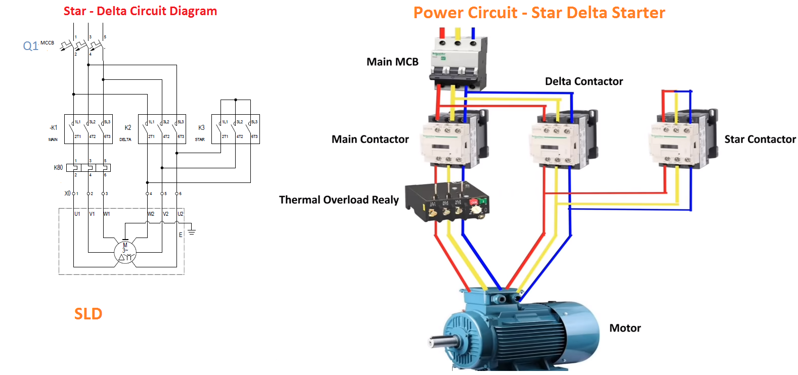
Star delta starters consist of a power circuit and control circuit.
Connect a thermal overload relay with the main contactor as shown in the above diagram. R , y, b = red, yellow, blue ( 3 phase lines)c.b = general circuit breakermain = mai supplyy = starδ = deltac1, c2, c3 = contatcors (power diagram)o/l = over load relayno = normally opennc = normally closed k1 = contactor (contactor coil) k1/no = contactor holding coil. Star delta starter control wiring. In star connected state, voltage applied is reduced to 1/√3 of the line voltage across each winding. To limit the starting current surge, large induction motors are started at reduced voltage and then have full supply voltage reconnected when they run up to near rotated speed. Next, the circuit goes through the nc terminals of the thermal over load relay. A wiring diagram usually gives opinion practically the relative direction and. In the above star delta starter control circuit wiring diagram with timer and normally close push buttonnormally open push button switch. How to wire star delta starter with three phase ac motors? Star delta starters consist of a power circuit and control circuit. Now, you have a total of six terminals to connect with the motor three from the output of the olr and three from the output of the delta contactor. Power and #control circuit.star delta starter control circuit #diagram star delta control circuit s. And also i will explain this starter connection step by ste.
The on delay timer diagram is also shown in the diagram. This energized star contactor coil and motor get connected in star. As you see in the above star delta starter diagram, first, an nc push button switch is connected to stop the operation. Star delta starter control circuit wiring diagram consist timer, push button for start and stop. R , y, b = red, yellow, blue ( 3 phase lines)c.b = general circuit breakermain = mai supplyy = starδ = deltac1, c2, c3 = contatcors (power diagram)o/l = over load relayno = normally opennc = normally closed k1 = contactor (contactor coil) k1/no = contactor holding coil.
How To Connect A Three Phase Induction Motor To A Star Delta Starter Properly If I Connect Wrongly Will It Change Direction Of Rotation Quora from qph.fs.quoracdn.net As and when motor attains good rotational speed, say about 90% of full r.p.m after few seconds, timer connected in starter disconnects star contactor first and then connects delta contactor. As shown in the fig. In control wiring diagram all magnetic contactors coils are rated 220 vac. And their applications with advantages. Next, the circuit goes through the nc terminals of the thermal over load relay. Drawings explained step by step. Dosto aaj ki is video me aap dekheenge star delta starter control circuit diagram or kaise kaam karta hai #stardeltastartercircuitsubscribe yk electrical for. Power and #control circuit.star delta starter control circuit #diagram star delta control circuit s.
In control wiring diagram all magnetic contactors coils are rated 220 vac.
In the above star delta starter control circuit wiring diagram with timer and normally close push buttonnormally open push button switch. Connect a thermal overload relay with the main contactor as shown in the above diagram. In the above star delta starter control circuit wiring diagram with timer and normally close push button/normally open push button switch. As and when motor attains good rotational speed, say about 90% of full r.p.m after few seconds, timer connected in starter disconnects star contactor first and then connects delta contactor. A 8 pin timer are used. Power and #control circuit.star delta starter control circuit #diagram star delta control circuit s. Next, the circuit goes through the nc terminals of the thermal over load relay. The control circuit uses to control the starter circuit such as on, off and tripping operations. The on delay timer diagram is also shown in the diagram. Now, you have a total of six terminals to connect with the motor three from the output of the olr and three from the output of the delta contactor. Connect those all terminal with the motor as shown in the above diagram. Star delta starter control circuit wiring diagram consist timer, push button for start and stop. This energized star contactor coil and motor get connected in star.
Drawings explained step by step. In star connected state, voltage applied is reduced to 1/√3 of the line voltage across each winding. When the fault occurs the thermal overload relay will trip the circuit. To limit the starting current surge, large induction motors are started at reduced voltage and then have full supply voltage reconnected when they run up to near rotated speed. Now, you have a total of six terminals to connect with the motor three from the output of the olr and three from the output of the delta contactor.
Using Star Delta Motor Control With Circuit Diagrams Turbofuture from images.saymedia-content.com Motor control panel wiring diagram pdf star delta starter electrical notes articles is one of the pictures that are related to the picture before in the collection gallery, uploaded by autocardesign.org.you can also look for some pictures that related to wiring diagram by scroll down to collection on below this picture. Star delta starter control wiring. Star delta starter control circuit wiring diagram consist timer, push button for start and stop. In the above star delta starter control circuit wiring diagram with timer and normally close push buttonnormally open push button switch. Dosto aaj ki is video me aap dekheenge star delta starter control circuit diagram or kaise kaam karta hai #stardeltastartercircuitsubscribe yk electrical for. In star delta starting an induction motor is connected i. And their applications with advantages. And also i will explain this starter connection step by ste.
Star delta starters consist of a power circuit and control circuit.
A 8 pin timer are used. As shown in the fig. Automatic star delta starter with timer for 3 phase ac motors in this tutorial we will enactment the star delta y 3 phase induction ac motor starting method by automatic star delta starter subsequently timer subsequent to schematic facility control and wiring diagram as competently as how star delta starter works and their applications in. Refer to the below star delta circuit, As you see in the above star delta starter diagram, first, an nc push button switch is connected to stop the operation. In control wiring diagram all magnetic contactors coils are rated 220 vac. In star delta starting an induction motor is connected i. In star connected state, voltage applied is reduced to 1/√3 of the line voltage across each winding. Star delta starters consist of a power circuit and control circuit. This energized star contactor coil and motor get connected in star. Between these two, star connected and delta connected states, circuit becomes open and motor neither. Star delta starter wiring diagram, this post is about the main wiring connection of three phase motor with star delta starter and control wiring diagram of 1 mccb circuit breaker 3 magnetic contactors 3 phase motor thermal overload relay / electronic overload relay ocr an on daily timer (8 pin timer. When the fault occurs the thermal overload relay will trip the circuit.
